


PAM-STAMP – Stamping Simulatin Solution
Sheet Metal Design & Forming Simulation Solution
With
our die face design and sheet metal forming simulation software
called PAM-STAMP,
engineers can design, optimize and verify sheet metal forming
processes on computer. PAM-STAMP covers
cold, warm and hot sheet metal and tube forming processes, patched
and tailored blanks, and is used in all metal forming industries,
including automotive, aerospace, electronics, and appliance.
At
the quoting stage,
users can determine blank outlines and optimum nesting for material
cost estimation, and quickly develop draw sheet metal forming
dies. In
the feasibility phase,
die designers can model tool surfaces based on B-Spline geometry, and
engineer a successful forming process without cracks and wrinkles, to
specifications, including hemming, trim development and trim line and
blank shape optimization. In
the validation phase,
engineers can precisely estimate springback, compensate the dies in
the drawing operation or across multi-operations, and detect and
visualize cosmetic defects just as they would on the shop floor.
There is no difference in any of the software settings between the
feasibility and validation phase, which ensures
the best possible result quality.
But
we do not stop here..
Validation
of the cooling efficiency of 3D tools in a press hardening process is
possible with
a heat transfer or a true fluid-flow (CFD) analysis. Also, since
manufacturing affects material properties, which in turn affect
product performance, the results of a forming process can be used to
engineer a welding
assembly process,
with the goal to keep the assembly within tolerances and improve
product performance. Finally, engineers can display
and review the findings in a virtual reality environment.
Virtual Prototyping ensures that component manufacturing and assembly
processes deliver the designed product specifications and performance
– on time, and within budget. ESI provides complete solutions for
virtual prototyping of lightweight designs that deliver as good as
real prototypes so designers can make the right decisions.
Read
Engineering.com’s article “Die
Face Design Solution Cuts Tooling Development Time”
to learn more about PAM-STAMP.
Read
More: ESI PAM-STAMP in Print
Automated
Die Face Design Provides Early Feasibility for Sheet Metal Stamping
Models
Tools
for Troubleshooting
Software
Assist Propels Hot-Forming Die Design and Build
Die
Face Design
Die Face Design and
manufacturing simulation solutions for metal forming from
PAM-DIEMAKER and PAM-TFA for Catia V5.
PAM-STAMP – Stamping Simulation Solution
From Design/Concept to Try-out
For any given metal forming process, it is possible today to conceive everything in a virtual engineering equivalent – from detailing customer requests to virtually inspecting the final product, as well as setting-up the production facilities. This includes material cost estimation, die design and feasibility, part design validation and tooling design and forming processes.
Below you will find a good selection of the milestones and elements of a virtual stamping engineering process that you can excel with stamping simulation software and solutions from ESI – from sheet metal stamp simulation to style,design, part and dies production – and beyond.
Making engineers productive – What is available and how does it work:
Navigation:
- Topology check, cleanup and repair
- Material cost estimation
- Die face design next generation based on B-Spline geometry
- Fast link with simulation
- Accurate numerical methodsAccurate Numerical Methods – Key for Accurate Virtual Prototyping
- Geometrical drawbeads
- Springback – Kinematic Hardening Model
- Ironing
- Triple speed mode for breathtaking short simulation times
- Springback – Kinematic Hardening Model
- Precise prediction of wrinkles including folding – no numerical flattening
- Blank & Trim Line Optimization
- (Multi-operation) compensation
- Virtual prototyping of the full stamping chain
- Cosmetic defects
- Customization
- High quality results without tradeoffs in cost and time
- Hot Forming, End-to-End Virtual Prototyping
- Chaining with manufacturing engineering and assembly prototyping
- Virtual Reality
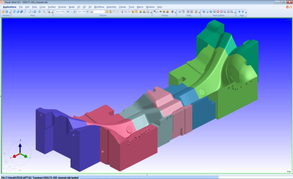
Topology check, cleanup and repair
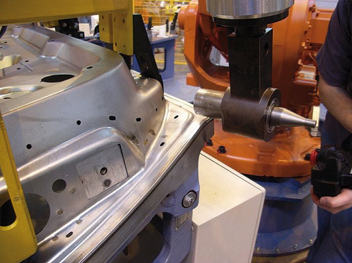
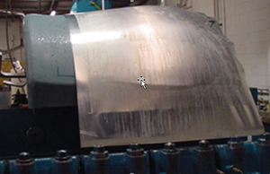
An accurate description of the contact surfaces as basis for an accurate mesh is the key to accurate results – from the beginning. Especially if one is forced to work with foreign die faces, and exchange data between different systems, topology problems in the geometry might occur. It might be necessary to fill holes and repair cracks or to improve geometry in a way that the meshing of the tool surface yields in the best possible simulation results.
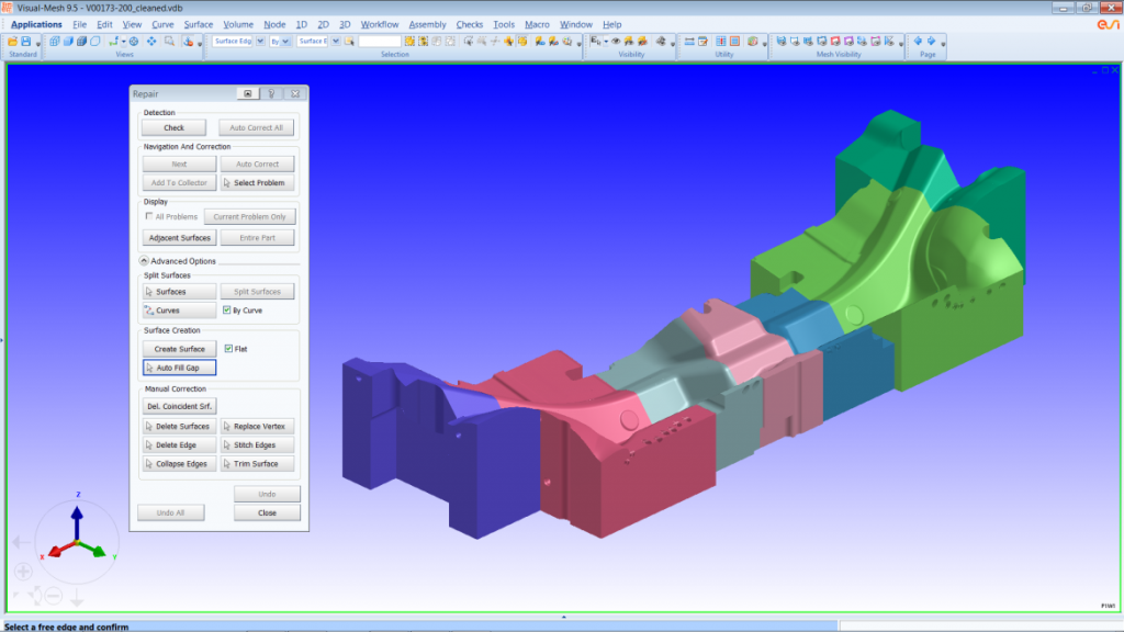
Lower part of a press hardening die of a dash panel – Control of topology and thus an accurate representation of contact surfaces guarantee accurate results – Courtesy AP&T
Of course one can always choose the automatic path – but in case of a low quality topology this might lead to a lower result quality and consequently in not identified cracks or wrinkles. In order to be able to work with the best possible topology, VISUAL MESH allows checking, clean up and repair of any topology in no time, before the simulation work starts. It is also possible to modify geometry, and to repair any kind of already generated meshes, no matter in which system they were done. In no time, any topology or mesh is in a status to provide best possible simulation results, using accurate contact.
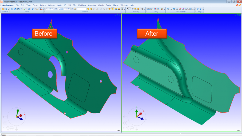
Topology repair to achieve a target stitching tolerance

Repair of missing or bad surfaces
Making engineers productive – What is available and how does it work:
Navigation:
- Topology check, cleanup and repair
- Material cost estimation
- Die face design next generation based on B-Spline geometry
- Fast link with simulation
- Accurate numerical methodsAccurate Numerical Methods – Key for Accurate Virtual Prototyping
- Geometrical drawbeads
- Springback – Kinematic Hardening Model
- Ironing
- Triple speed mode for breathtaking short simulation times
- Springback – Kinematic Hardening Model
- Precise prediction of wrinkles including folding – no numerical flattening
- Blank & Trim Line Optimization
- (Multi-operation) compensation
- Virtual prototyping of the full stamping chain
- Cosmetic defects
- Customization
- High quality results without tradeoffs in cost and time
- Hot Forming, End-to-End Virtual Prototyping
- Chaining with manufacturing engineering and assembly prototyping
- Virtual Reality
Material cost estimation
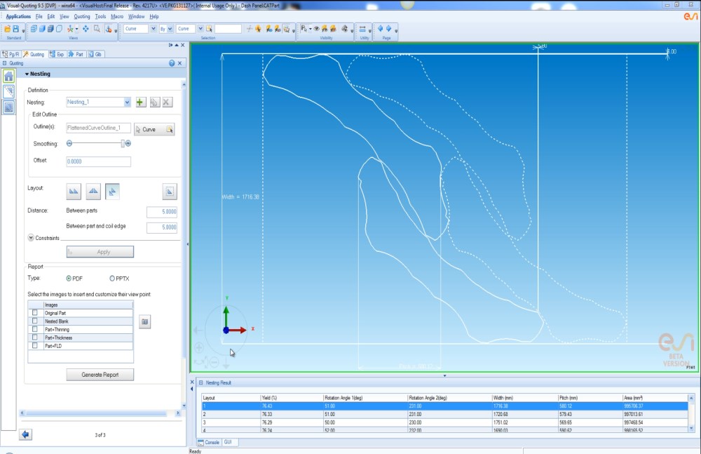
Car bodies are made from a few hundreds metal parts. In the production process, these three-dimensional parts are cut from two-dimensional sheet metal before they are press-formed and (spot- or laser) welded together by robots. The two-dimensional sheet metal is available as long rolls, better known as ‘coils’, which can have different widths, numerous material properties and variable prices and nowadays can even have different thickness along the roll. Taking the full part geometry as a starting point, the application can quickly develop the flattened blank outline and determine the optimal nesting layout in the coil corresponding to the lowest material cost. The following describes in few sentences the general workflow and available functionalities to effectively perform the job-to-be-done.
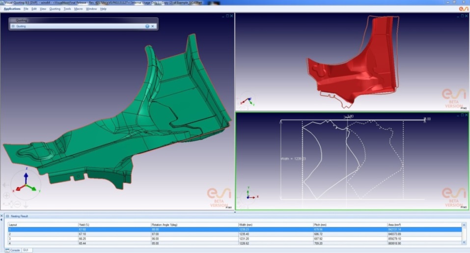
Material cost estimation – Blank outline and nesting
Part Geometry Definition
The part can be imported as a surface or solid model. Dedicated functionality for extracting the top and bottom surface of the solid model, as well as generation of the mid-surface are available in order to calculate correctly the flattening of the part geometry at the neutral fiber. The selected part can be assigned with required material and thickness information.
Blank Outline Definition
The bidding solution is based on ESI GROUP’s best-in-class one-step solver. In the shortest possible time it determines accurately the flattened blank outline (even if undercut areas exist), based on the full 3-D part model and few process parameters like binder force, material definition and thickness. In addition to the developed blank outline, part feasibility can also be directly and thoroughly analyzed through various contours like thinning, thickness and forming limit diagram (FLD). Direct import of a blank outline is supported as well.
Nesting
The developed blank outline can be used in the nesting process. The outline can be smoothened and can be applied with or without addendum region generation through constant offset of the outline. Multiple nesting layouts are supported like “One up”, “Two up”, “Mirror” and “Transfer Die” for optimal material utilization calculation.
Automatic Reporting
The solution includes a fast and automated report generator for quotation of the part material. This functionality includes export of material utilization, fall off, pitch, coil width, blank area and pictures of the nesting sequence and developed blank outline.
Making engineers productive – What is available and how does it work:
Navigation:
- Topology check, cleanup and repair
- Material cost estimation
- Die face design next generation based on B-Spline geometry
- Fast link with simulation
- Accurate numerical methodsAccurate Numerical Methods – Key for Accurate Virtual Prototyping
- Geometrical drawbeads
- Springback – Kinematic Hardening Model
- Ironing
- Triple speed mode for breathtaking short simulation times
- Springback – Kinematic Hardening Model
- Precise prediction of wrinkles including folding – no numerical flattening
- Blank & Trim Line Optimization
- (Multi-operation) compensation
- Virtual prototyping of the full stamping chain
- Cosmetic defects
- Customization
- High quality results without tradeoffs in cost and time
- Hot Forming, End-to-End Virtual Prototyping
- Chaining with manufacturing engineering and assembly prototyping
- Virtual Reality
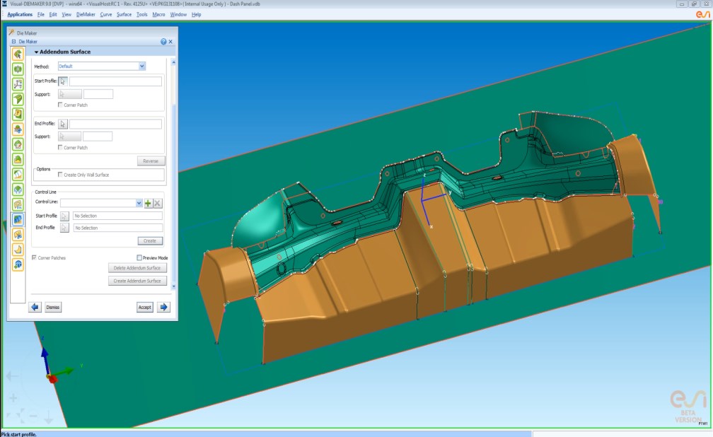
Die face design next generation based on B-Spline geometry
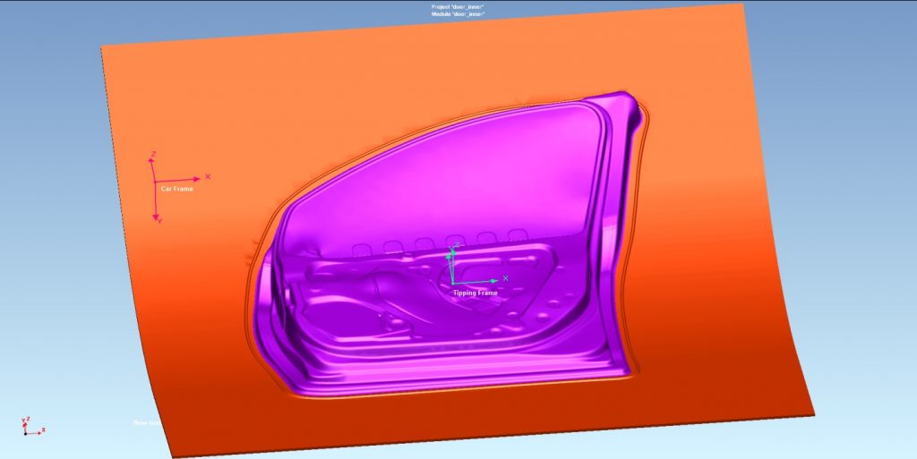
Nowadays die face design is moving towards CAD environment. Iterations are done directly inside CAD and on native CAD data. The tool used for die face design must support the user in all phases of the process design cycle: from the very early conception phase, through feasibility studies until the final validation. An optimum with respect to performance and accuracy needs to be established for each of these separate steps. Die face design should be based on B-Spline geometry in order to keep the solution fast, powerful, flexible and compliant to the automotive industry standards. Any possible hold due to required changes in geometry must be removed. Surfaces must be accurate to guarantee an accurate description of contact surfaces and accurate simulation results – as early as possible
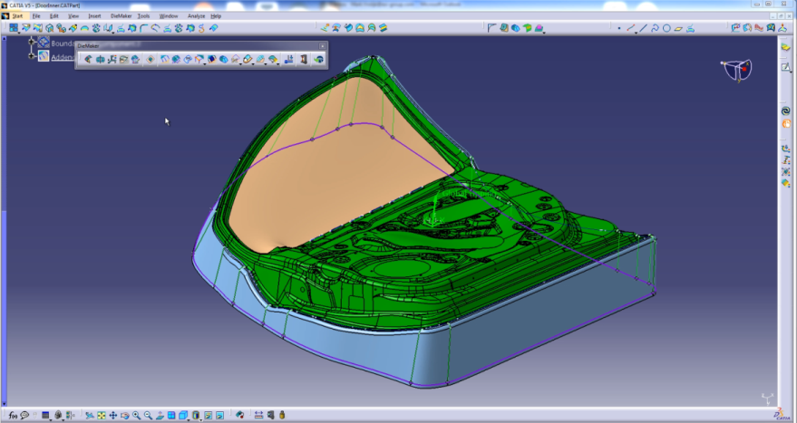
Die face of a door inner – Based on B-spline geometry
Customer Challenge
Automotive sheet metal forming parts come from the design department and often consider only aesthetics (outer panels) or functionality (reinforcements, beams etc.). Normally no, or very little, consideration is given to manufacturability. This is the job of the process design department or toolmaker: find ways to create the part in a robust and cost-optimized way. In most cases the time-pressure is huge (and ever increasing), but still many variants of the die face design and process need to be considered before an optimum (manufacturability and cost!) is found.
Typical Workflow
Starting from the part geometry, a first die face design for the first draw die is quickly drafted and evaluated for general feasibility like occurrences of cracks and wrinkles. As the first design will not normally fulfil all criteria, iteration loops are run to optimize the die face design and stamping process parameters. These iterations normally consist out of the following:
Complete or partial part modifications coming from the design department
Geometrical addendum modifications to eliminate wrinkles, cracks or to optimize the trimming conditions
Process modifications to overcome cracks and wrinkles and improve the general robustness of the process
Reduction of blank size for material cost optimization
Propose part modifications in case a feasible or robust process cannot be guaranteed
After proof of concept of the general feasibility for the first drawing stage, the following operations are included in the process design (trimming, hemming, flanging, restrike…), both geometrical design and simulation validation. Next to the crack and wrinkle analysis and press force estimation, other criteria also become relevant at this stage, e.g. analysis including cosmetic defects for outer panels and springback compensation for the forming dies. Finally, the last step, after full validation of the process design, milling of the production tools will be carried out.
Key Capabilities
Integration of a dedicated solution for die face design into CAD environments will offer huge advantages over standard CAD usage and mesh-based die face design solutions:
Compared to standard CAD usage, it minimizes the tool designers’ workload by implementing tool design & process knowledge, and following the natural process of tool face design.
The integration offers a set of powerful interactive tools and functions, which provide guidance and support for part preparation, binder development and die addendum and provides quick access to important process information like trimming angle conditions and developed trimline geometry.
It combines the convenience and speed of rapid die face design with the quality of the native CAD surfacing. Therefore highest quality simulation results can be expected – right from the beginning.
Full CAD based design eliminates the need to regenerate a mesh model in CAD and thus doing the same work twice. The same model can be used throughout all phases of the development process, from the early (feasibility) stage up to the milling of the model
Due to the CAD integration all native CAD functionalities can be used to reach an optimal design without need for compromises due to limitations of the mesh-based die face design software
Easy and fast iterations due to dedicated part replace functionality: in just a few minutes, the original part geometry can be exchanged with the latest version of the part. There is no need to reconstruct manually the full die any more.
By providing a strong dedicated link to the simulation environment, quick and easy simulation iterations can be carried out without the need for much user interaction and without loss of geometrical accuracy
Major Benefits
Reduction of costs, by using the state-of-the-art die face development methods to deliver right the first time
Ensuring success in prototyping and manufacturing by testing the virtual prototype first: production problems avoidance strategy
Gain time: no need to rebuild die face designs in CAD environment based on a mesh reference
Also in the last phase of the development process new part variants can still be easily and quickly investigated by integrated intuitive replace functionality for CAD data
Fast learning curve for new users: with only very little training also non CAD experts can become extremely efficient in creating production ready die face designs
The die face design product can be easily integrated into the existing host PLM structure
Making engineers productive – What is available and how does it work:
Navigation:
- Topology check, cleanup and repair
- Material cost estimation
- Die face design next generation based on B-Spline geometry
- Fast link with simulation
- Accurate numerical methodsAccurate Numerical Methods – Key for Accurate Virtual Prototyping
- Geometrical drawbeads
- Springback – Kinematic Hardening Model
- Ironing
- Triple speed mode for breathtaking short simulation times
- Springback – Kinematic Hardening Model
- Precise prediction of wrinkles including folding – no numerical flattening
- Blank & Trim Line Optimization
- (Multi-operation) compensation
- Virtual prototyping of the full stamping chain
- Cosmetic defects
- Customization
- High quality results without tradeoffs in cost and time
- Hot Forming, End-to-End Virtual Prototyping
- Chaining with manufacturing engineering and assembly prototyping
- Virtual Reality
Fast link with simulation
Fast Link with Simulation to Minimize the Time to set up a Simulation and Spent for Iterations
Support for the many iterations, which is characteristic of the early design phase of a car project, is covered through a dedicated link between both the die face design and the simulation environment. The final goal of virtual prototyping is to get the part out of the press ‘right first time’.
In the middle of a die face process – Fast iterations without trade-offs in result quality
However, this requires beforehand a fast number of iterations within the simulation environment to come to a robust and feasible solution for the production of the component. The first simulation will usually be far from the final feasible design. In addition, the part geometry itself will frequently change during in this phase: small features can be added or removed, or parts can be completely re-designed. Historically the CAD model of the tool was imported without additional supporting information. A blank outline and drawbeads had to be defined along with their data and properties, resulting in time-consuming generation of the final tooling. This resulted in cumbersome and time-consuming iteration with a lot of manual work for the engineer, and with a huge risk for project delays and budget overspending. On top of that, also errors appeared between subsequent iterations. All of ESI-Group’s solutions for die face design are currently embedded in a CAD environment (CATIA V5 and VISUAL). They include a streamlined and efficient transition between die face design and the simulation based analysis tool, by reducing the amount of required user-interaction to an absolute minimum.
The quick link with simulation saves up to 80% of the time needed for setting up a draw die simulation. Not only are geometrical data (like punch and binder geometry) transferred, but also process data like binder forces, binder travel distances, part material definition and thickness and material offset direction and finally car and tipping system of coordinates are kept in order to enable advanced inter-disciplinary engineering.
Making engineers productive – What is available and how does it work:
Navigation:
- Topology check, cleanup and repair
- Material cost estimation
- Die face design next generation based on B-Spline geometry
- Fast link with simulation
- Accurate numerical methodsAccurate Numerical Methods – Key for Accurate Virtual Prototyping
- Geometrical drawbeads
- Springback – Kinematic Hardening Model
- Ironing
- Triple speed mode for breathtaking short simulation times
- Springback – Kinematic Hardening Model
- Precise prediction of wrinkles including folding – no numerical flattening
- Blank & Trim Line Optimization
- (Multi-operation) compensation
- Virtual prototyping of the full stamping chain
- Cosmetic defects
- Customization
- High quality results without tradeoffs in cost and time
- Hot Forming, End-to-End Virtual Prototyping
- Chaining with manufacturing engineering and assembly prototyping
- Virtual Reality
Accurate numerical methodsAccurate Numerical Methods – Key for Accurate Virtual Prototyping
Accurate contact permanently prohibits the nodes of the blank sheet from any penetration of the volume of the element of the tool during a calculation. The nodes are kept exactly at the surface of the element owing to the contact forces being precisely calculated.
Today, all explicit simulations in PAM-STAMP are carried out with accurate contact and high quality numerical settings, no matter if in the feasibility or validation stage. Accurate contact is applied to huge simulation models with one million or more elements. At the same time, the explicit method with many short time steps allows for the precise integration of the material history in the drawing phase. It is not possible to run accurate contact with many short time steps on large models with implicit solutions because it would be too time consuming.
Working with accurate contact, short time steps to integrate the material law accurately and from the beginning accurate numerical settings has several advantages:
There is no risk of finding – late and thus costly – issues like cracks or wrinkles in the validation phase, just because of different (contact or numerical) settings in the feasibility stage. Accurate contact in all simulation stages and providing an accurate representation of the tool topology and tool mesh from the beginning helps to avoid this problem, which otherwise can take a lot of time to compensate for the encountered issues.
The accurate computation of plasticity and residual stresses after forming is guaranteed, which is the pre-condition of accurate springback.
This accurate springback is the best basis for predictive distortion compensation on the forming side of life or in the final assembly process (hot and cold joining)
Accurate springback means accurate residual stresses and plastic history – which are the required basis for predictive performance simulations
The ironing effect can be taken into account
The press force is predicted precisely
Accurate contact and ironing are the basis for accurate die spotting – which can save a lot of time especially in the development of a press hardening die
Accurate contact is relatively computational intensive. However, with the new triple speed mode in PAM-STAMP (referred to later on in this document), simulations with accurate numerical settings are now also possible even in the earliest stage of the project. Consequently, any numerical compromises in the feasibility stage can now be discarded.
Making engineers productive – What is available and how does it work:
Navigation:
- Topology check, cleanup and repair
- Material cost estimation
- Die face design next generation based on B-Spline geometry
- Fast link with simulation
- Accurate numerical methodsAccurate Numerical Methods – Key for Accurate Virtual Prototyping
- Geometrical drawbeads
- Springback – Kinematic Hardening Model
- Ironing
- Triple speed mode for breathtaking short simulation times
- Springback – Kinematic Hardening Model
- Precise prediction of wrinkles including folding – no numerical flattening
- Blank & Trim Line Optimization
- (Multi-operation) compensation
- Virtual prototyping of the full stamping chain
- Cosmetic defects
- Customization
- High quality results without tradeoffs in cost and time
- Hot Forming, End-to-End Virtual Prototyping
- Chaining with manufacturing engineering and assembly prototyping
- Virtual Reality
Geometrical drawbeads
Geometrical drawbeads are well managed with accura-te contact. This further contributes to the high quality of computed results. The new triple speed mode provi-des short response time without trade-off in re-sult quality. Simplifications are not necessary any more.
Geometrical drawbeads in simulation
Making engineers productive – What is available and how does it work:
Navigation:
- Topology check, cleanup and repair
- Material cost estimation
- Die face design next generation based on B-Spline geometry
- Fast link with simulation
- Accurate numerical methodsAccurate Numerical Methods – Key for Accurate Virtual Prototyping
- Geometrical drawbeads
- Springback – Kinematic Hardening Model
- Ironing
- Triple speed mode for breathtaking short simulation times
- Springback – Kinematic Hardening Model
- Precise prediction of wrinkles including folding – no numerical flattening
- Blank & Trim Line Optimization
- (Multi-operation) compensation
- Virtual prototyping of the full stamping chain
- Cosmetic defects
- Customization
- High quality results without tradeoffs in cost and time
- Hot Forming, End-to-End Virtual Prototyping
- Chaining with manufacturing engineering and assembly prototyping
- Virtual Reality
Springback – Kinematic Hardening Model
Residual stresses inside the sheet metal, after stamping just before tool’s removal, cause ‘Springback’. Consequently, accurate springback prediction requires accurate stress prediction during stamping. However, conventional material models like isotropic hardening cannot predict the stress accurately. The following figure, quoted from the lecture note by Prof. Yoshida in Hiroshima University, explains why the cyclic stress-strain path during stamping is important for the springback analysis.
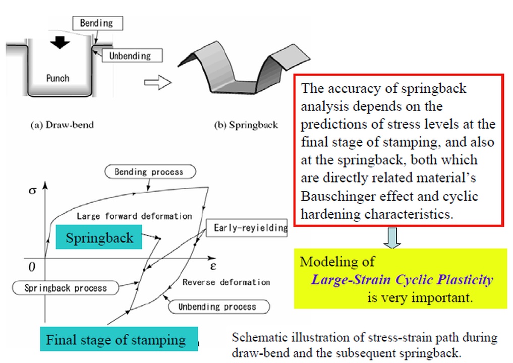
Importance of modelling for large strain cyclic plasticity
Yoshida-Uemori (Y-U) Kinematic Hardening Model
To describe the material behavior under cyclic deformation accurately, the Bauschinger effect must be taken into account in the material model. For that purpose, a kinematic hardening (KH) model is employed instead of an isotropic hardening model. The Yoshida-Uemori model is the best one for sheet metal forming among existing KH models. This is because the Y-U model involves only seven parameters of cyclic plasticity, and each parameter has a physical definition. There are no artificial mathematical parameters. In addition, a Young’s modulus depending on plastic strain is introduced in the model to describe stress-strain response more accurately after stress reversal.
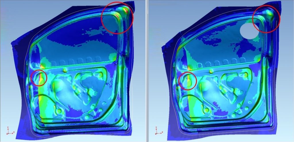
The following images illustrate the effectiveness of Y-U model on prediction of springback, which is reported by TOA Industries Co., Ltd. Thanks to Y-U model, springback prediction accuracy on B-Pillar Inner panel with 980MPa High Strength Steel dramatically improved. Consequently, TOA Industries succeeded in reducing the physical tryout.
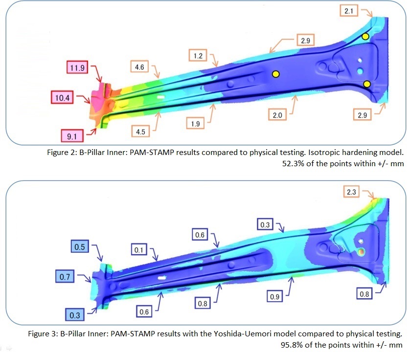
Improvement of springback accuracy by Y-U model Courtesy of TOA Industries
Material Parameter Identification by ‘MatPara’
If the material test and parameters identification are difficult, it is difficult to use a material model in production, even though the material model itself can give results that are more accurate. Thanks to ‘MatPara’ developed by Prof. Yoshida and distributed by ESI Group, material parameters for the Y-U model can be easily identified. The following figure shows ‘MatPara’, where Y-U parameters are calculated from the material tests that include cyclic tension-compression and tensile test until rupture. Thanks to a material database inside ‘MatPara’ and a strong optimization technology behind the software, Y-U parameters can be estimated even when only tensile test results are known.
Y-U model
Making engineers productive – What is available and how does it work:
Navigation:
- Topology check, cleanup and repair
- Material cost estimation
- Die face design next generation based on B-Spline geometry
- Fast link with simulation
- Accurate numerical methodsAccurate Numerical Methods – Key for Accurate Virtual Prototyping
- Geometrical drawbeads
- Springback – Kinematic Hardening Model
- Ironing
- Triple speed mode for breathtaking short simulation times
- Springback – Kinematic Hardening Model
- Precise prediction of wrinkles including folding – no numerical flattening
- Blank & Trim Line Optimization
- (Multi-operation) compensation
- Virtual prototyping of the full stamping chain
- Cosmetic defects
- Customization
- High quality results without tradeoffs in cost and time
- Hot Forming, End-to-End Virtual Prototyping
- Chaining with manufacturing engineering and assembly prototyping
- Virtual Reality
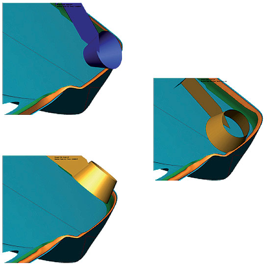
Ironing
Ironing is used to control springback – in particular with high strength steel – and a natural phenomenon in processes like coining.
Precision forming of processes where ironing or coining occurs requires the use of a particular Finite Element (FE) formulation, which takes into account through thickness stress.
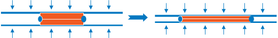
Coining

Ironing
The normal shell formulation is not sufficient to describe this phenomena, as the stress and strains in the element normal are not described good enough. Therefore, PAM-STAMP features a particular element to simulate ironing: TTS – Through Thickness Stress element.
This element takes into account thinning, normal stress and 3D plasticity induced by bilateral contacts. It is activated automatically when ironing phenomena appears. It is compatible with Yoshida kinematic hardening model, means it can be used for advanced springback simulations.
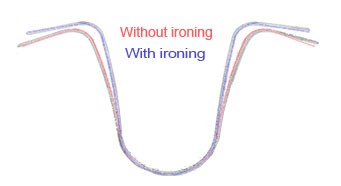
Grey: real test with/without ironingRed: PAM-STAMP results without ironingBlue: PAM-STAMP results with ironing
Making engineers productive – What is available and how does it work:
Navigation:
- Topology check, cleanup and repair
- Material cost estimation
- Die face design next generation based on B-Spline geometry
- Fast link with simulation
- Accurate numerical methodsAccurate Numerical Methods – Key for Accurate Virtual Prototyping
- Geometrical drawbeads
- Springback – Kinematic Hardening Model
- Ironing
- Triple speed mode for breathtaking short simulation times
- Springback – Kinematic Hardening Model
- Precise prediction of wrinkles including folding – no numerical flattening
- Blank & Trim Line Optimization
- (Multi-operation) compensation
- Virtual prototyping of the full stamping chain
- Cosmetic defects
- Customization
- High quality results without tradeoffs in cost and time
- Hot Forming, End-to-End Virtual Prototyping
- Chaining with manufacturing engineering and assembly prototyping
- Virtual Reality
Triple speed mode for breathtaking short simulation times

Triple Speed Mode for Explicit Simulations
A new solver option in PAM-STAMP allows analysis speed up in the same manner as conventional numerical tuning, but without a loss in quality. Specifically, a 3-4X analysis speed up in the drawing phase, with no associated loss of quality, allows these high quality feasibility studies to be completed within the same time constraints as conventional feasibility studies.
In combination with multi-core processors, very short simulation times can be achieved. With the new solver option and a four core CPU, a total speed up of 12-15 X is possible compared to a one core simulation without the new solver option. Simulation times are now short enough for formability stage precision to be used in the early feasibility phase – all with precision forming quality provided by PAM-STAMP. Consequently, it is no longer necessary to tune explicitly simulations by numerical means i.e. mass scaling, numerical settings, mesh coarsening etc. – to achieve feasibility run time and consequently pay with a loss of quality. Moderate baseline settings can be used in the feasibility stage. Because the new solver development is not at the expense of quality, it is also applicable in the validation / formability phase. Consequently, it is possible to achieve, with standard baseline settings for conservative engineering, the same simulation time as with tuned baseline settings, or even less. With the new solver, it is also no longer necessary to use coarser meshes or any other kind of model simplifications to achieve less simulation time. This allows for high-quality results with a reasonable simulation time at the earliest stage possible. The figure below shows an efficiency of the triple speed mode. The model used for the verification was provided from Mitsubishi Motors. Without loss of quality, calculations with triple speed mode are faster by a factor of 3.7 compared to the normal mode.
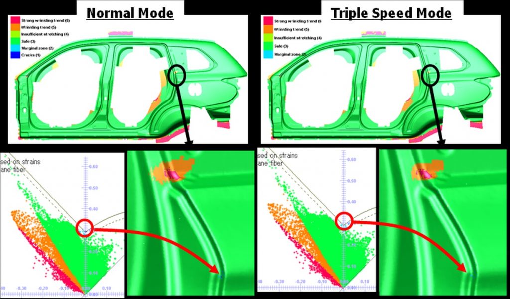
| Stage | Calcultion time (h) | Calcultion time (h) | Ratio | Calculation type |
| Normal | Triple | |||
| Restrike | 4.11 | 1.1 | 3.74 | DMP 4 cores |
Simulations with Triple Speed mode, Courtesy of Mitsubishi Motors
Making engineers productive – What is available and how does it work:
Navigation:
- Topology check, cleanup and repair
- Material cost estimation
- Die face design next generation based on B-Spline geometry
- Fast link with simulation
- Accurate numerical methodsAccurate Numerical Methods – Key for Accurate Virtual Prototyping
- Geometrical drawbeads
- Springback – Kinematic Hardening Model
- Ironing
- Triple speed mode for breathtaking short simulation times
- Springback – Kinematic Hardening Model
- Precise prediction of wrinkles including folding – no numerical flattening
- Blank & Trim Line Optimization
- (Multi-operation) compensation
- Virtual prototyping of the full stamping chain
- Cosmetic defects
- Customization
- High quality results without tradeoffs in cost and time
- Hot Forming, End-to-End Virtual Prototyping
- Chaining with manufacturing engineering and assembly prototyping
- Virtual Reality
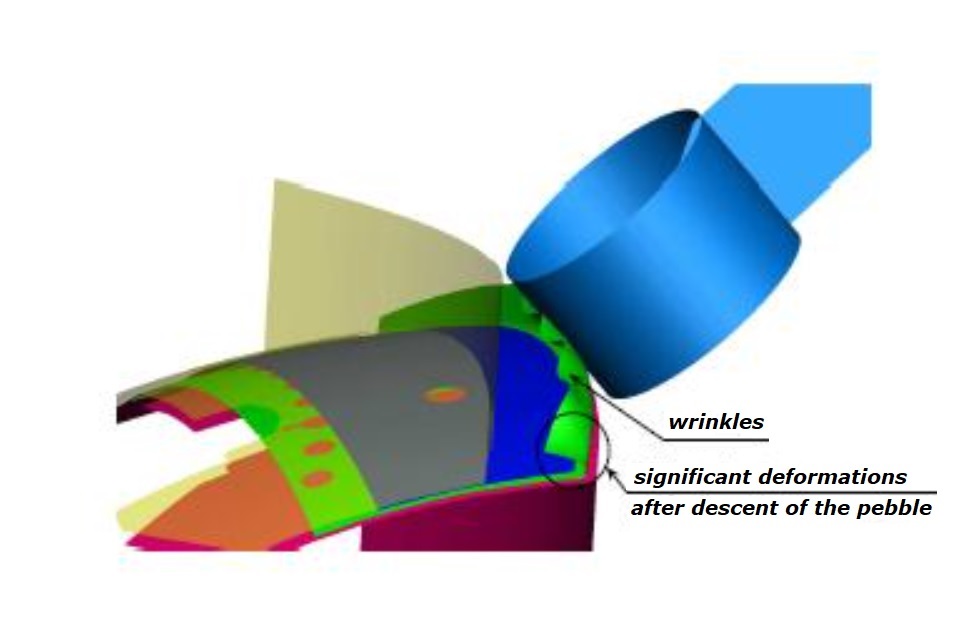
Precise prediction of wrinkles including folding – no numerical flattening
Wrinkles
Especially in a hot forming process, wrinkles can come and go. In case not flattened out at the end they could even destroy a die. PAM-STAMP simulates wrinkles with no compromises – as they would occur in reality, including folding. Only an explicit simulation scheme can do that – thanks to the many small time steps and the ability to manage significant geometrical non-linearity’s without slowing down or even stop the simulation.
Evolution of wrinkles during forming – Courtesy AP&T
Making engineers productive – What is available and how does it work:
Navigation:
- Topology check, cleanup and repair
- Material cost estimation
- Die face design next generation based on B-Spline geometry
- Fast link with simulation
- Accurate numerical methodsAccurate Numerical Methods – Key for Accurate Virtual Prototyping
- Geometrical drawbeads
- Springback – Kinematic Hardening Model
- Ironing
- Triple speed mode for breathtaking short simulation times
- Springback – Kinematic Hardening Model
- Precise prediction of wrinkles including folding – no numerical flattening
- Blank & Trim Line Optimization
- (Multi-operation) compensation
- Virtual prototyping of the full stamping chain
- Cosmetic defects
- Customization
- High quality results without tradeoffs in cost and time
- Hot Forming, End-to-End Virtual Prototyping
- Chaining with manufacturing engineering and assembly prototyping
- Virtual Reality
Blank & Trim Line Optimization
Optimisation of stamping process parameters, such as forces, and drawbeads, and subsequent checking of the robustness of the process to natural variations in material properties and process variables is slowly being adopted, as computer hardware and software technology evolve in synergy to reduce calculation times, optimisation and robustness assessments become a logical extension of forming simulation.
An automatic optimization module runs iterations until a good result is found. Optimized blank shape and trim line helps saving material and reducing trimming operations.
Blank & Trim Line Optimization
Making engineers productive – What is available and how does it work:
Navigation:
- Topology check, cleanup and repair
- Material cost estimation
- Die face design next generation based on B-Spline geometry
- Fast link with simulation
- Accurate numerical methodsAccurate Numerical Methods – Key for Accurate Virtual Prototyping
- Geometrical drawbeads
- Springback – Kinematic Hardening Model
- Ironing
- Triple speed mode for breathtaking short simulation times
- Springback – Kinematic Hardening Model
- Precise prediction of wrinkles including folding – no numerical flattening
- Blank & Trim Line Optimization
- (Multi-operation) compensation
- Virtual prototyping of the full stamping chain
- Cosmetic defects
- Customization
- High quality results without tradeoffs in cost and time
- Hot Forming, End-to-End Virtual Prototyping
- Chaining with manufacturing engineering and assembly prototyping
- Virtual Reality
Springback of High Strength Steel
Springback of High Strength Steel with PAM-STAMP
Modern requirements in automotive and aerospace industries mean higher strength with reduced weight. This means increased use of high strength steel and aluminium parts in modern vehicle structures. The problem of springback has come to the forefront of the die engineering process. The degree of springback experienced with the latest generation materials is so high, and the materials so strong, that it is not possible to ‘correct’ the springback in the prototyping, it becomes mandatory to compensate for springback as part of the draw die design.
Characteristic of Ultra High Strength Steel
High Yield Stress
Bad Formability
Large Springback
PAM-STAMP has in the recent years seen several improvements to help the engineer master the springback:
Automatic die compensation module
Yoshida-Uemori material model well suited for simulation of springback in HSS
Accurate contact formulations
Buckling detection
Bottoming detection
Through thickness stress element for simulation of bottoming and ironing effects
Making engineers productive – What is available and how does it work:
Navigation:
- Topology check, cleanup and repair
- Material cost estimation
- Die face design next generation based on B-Spline geometry
- Fast link with simulation
- Accurate numerical methodsAccurate Numerical Methods – Key for Accurate Virtual Prototyping
- Geometrical drawbeads
- Springback – Kinematic Hardening Model
- Ironing
- Triple speed mode for breathtaking short simulation times
- Springback – Kinematic Hardening Model
- Precise prediction of wrinkles including folding – no numerical flattening
- Blank & Trim Line Optimization
- (Multi-operation) compensation
- Virtual prototyping of the full stamping chain
- Cosmetic defects
- Customization
- High quality results without tradeoffs in cost and time
- Hot Forming, End-to-End Virtual Prototyping
- Chaining with manufacturing engineering and assembly prototyping
- Virtual Reality
(Multi-operation) compensation
(Multi-Operation) Die Compensation with PAM-STAMP
As well as for the evaluation of cosmetic defects, accurate modeling and a good process for the draw die is the precondition for successful compensation.
Before compensation
After compensation
A part with 20mm springback – as an example – should not be compensated. Compensation can be applied to the drawing operation, or across multiple operations, with various strategies.
Compensation schemes available in PAM-STAMP
Arcelor and Renault validated springback compensation method for several parts
Roof cross member, HE450M (FB600), thickness 1.8 mm, Courtesy of Renault
B-Pillar reinforcement, steel grade: TRIP 800, thickness 1.2 mm
Atlas Tool, Inc. Develops a Sound Springback Compensation Process with the Help of PAM-STAMP Software
Download the full Customer Success
“Advanced high-strength steels and particularly dual-phase steels are being utilized more and more by OEMs to improve safety, reduce weight and lower cost. The use of an advanced incremental simulation tool enables us to overcome the formability challenges posed by these materials and meet our customers’ requirements in as little time as possible. We believe our expertise with PAM-STAMP is a significant competitive advantage.”
Mark R. Schmidt, Atlas Tool’s President
Making engineers productive – What is available and how does it work:
Navigation:
- Topology check, cleanup and repair
- Material cost estimation
- Die face design next generation based on B-Spline geometry
- Fast link with simulation
- Accurate numerical methodsAccurate Numerical Methods – Key for Accurate Virtual Prototyping
- Geometrical drawbeads
- Springback – Kinematic Hardening Model
- Ironing
- Triple speed mode for breathtaking short simulation times
- Springback – Kinematic Hardening Model
- Precise prediction of wrinkles including folding – no numerical flattening
- Blank & Trim Line Optimization
- (Multi-operation) compensation
- Virtual prototyping of the full stamping chain
- Cosmetic defects
- Customization
- High quality results without tradeoffs in cost and time
- Hot Forming, End-to-End Virtual Prototyping
- Chaining with manufacturing engineering and assembly prototyping
- Virtual Reality
Virtual prototyping of the full stamping chain
Virtual Prototyping of the Full Stamping Chain with PAM-STAMP
In the early days of simulation, it was about simulating the forming stage with the objective to eliminate cracks and wrinkles. Then simulation technique moved on to springback and the compensation thereof. With PAM-STAMP it is possible to do a full virtual prototyping of the whole stamping chain, including:
Forming and springback
Restrike and springback
Flanging and springback
Hemming and springback
This allows the engineer to have full control over the whole stamping process, ensuring highest quality and no “surprises” during physical prototyping.
Courtesy of Hyundai
Precise Engineering Cuts Progressive Die Start-Up Costs by 80% with PAM-STAMP Stamping Simulation Solution
Download the full Customer Success
Computer simulation reduced the amount of time and money required to determine a successful forming process based on the defined stock width from an estimated $18,000 to only $3,600, concluded Rick Barnard, Precise Engineering’s General Manager. “The key to these savings was the use of PAM-STAMP to quickly and inexpensively simulate the performance of a wide range of die designs. Creating a virtual reality progressive die takes the try-out process off the shop floor and into the engineering office where it can be carried out faster and without tying up presses. We determined the process, developed the initial blank, accurately determined the flow of material during the first draw form, evaluated the impact of springback on finished tolerances, and monitored thinning percentages before we even began building the die.
Making engineers productive – What is available and how does it work:
Navigation:
- Topology check, cleanup and repair
- Material cost estimation
- Die face design next generation based on B-Spline geometry
- Fast link with simulation
- Accurate numerical methodsAccurate Numerical Methods – Key for Accurate Virtual Prototyping
- Geometrical drawbeads
- Springback – Kinematic Hardening Model
- Ironing
- Triple speed mode for breathtaking short simulation times
- Springback – Kinematic Hardening Model
- Precise prediction of wrinkles including folding – no numerical flattening
- Blank & Trim Line Optimization
- (Multi-operation) compensation
- Virtual prototyping of the full stamping chain
- Cosmetic defects
- Customization
- High quality results without tradeoffs in cost and time
- Hot Forming, End-to-End Virtual Prototyping
- Chaining with manufacturing engineering and assembly prototyping
- Virtual Reality
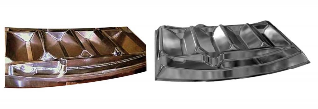
Cosmetic defects
Cosmetic Defect Prediction with PAM-STAMP
The apparition of cosmetic defects is deeply linked to springback phenomenon. The detection of such small defects is thus only possible with a very precise simulation of springback, which has been proved to be possible with PAM-STAMP. It features new dedicated defect contours based on stoning or sensor for detection of the defects and their quantification. With such contour the user can easily localize the defects as it is done in workshop and measure their depth and area.
Cosmetic Defect Prediction
AETHRA Automotive Systems anticipates critical aspect issues on large automotive body components with PAM-STAMP
Download the full Customer Success
AETHRA Automotive Systems, with the help of ESI South America in Brazil, significantly improved the results in prediction and resolution of surface defects in external panels using PAM-STAMP . Nowadays, to satisfy customer needs, we can test different strategies in the process development because we have confidence that we’ll see the same behavior in try-out.
A. Micheletti Viana, Mechanical Engineering – Formability
Wellington Caetano Soares, Mechanical Engineering – Formability
Arlem Picinin Campos, Simulation Manager
Typical problems in external panels can be predicted with simulation
Making engineers productive – What is available and how does it work:
Navigation:
- Topology check, cleanup and repair
- Material cost estimation
- Die face design next generation based on B-Spline geometry
- Fast link with simulation
- Accurate numerical methodsAccurate Numerical Methods – Key for Accurate Virtual Prototyping
- Geometrical drawbeads
- Springback – Kinematic Hardening Model
- Ironing
- Triple speed mode for breathtaking short simulation times
- Springback – Kinematic Hardening Model
- Precise prediction of wrinkles including folding – no numerical flattening
- Blank & Trim Line Optimization
- (Multi-operation) compensation
- Virtual prototyping of the full stamping chain
- Cosmetic defects
- Customization
- High quality results without tradeoffs in cost and time
- Hot Forming, End-to-End Virtual Prototyping
- Chaining with manufacturing engineering and assembly prototyping
- Virtual Reality
Customization
It is possible to customize PAM-STAMP with dedicated toolbars and process macros. This allows you to simplify and automate any stamping process.
Customization of a toolbar to set up single and double action processes
Process macros allow the customization of any die operation or complete process in a way that users must fill only actual process data to complete the setup of a process simulation. Consequently, no knowledge in the methods of Finite Elements or numerical methods is needed to set up and run a process simulation.
Customization of a toolbar to set up single and double action processes
Customizable key board shortcuts allow 1-click data check or post-processing.
Customization of a toolbar to set up single and double action processes
You can also add external programs to drive for example the solver or schedule jobs.
Customization of a toolbar to set up single and double action processes
Job scheduling
It is even possible to move PAM-STAMP in the background of completely customized processes in Visual Environment.
Integration of PAM-STAMP in a process environment dedicated to aerospace processes
Making engineers productive – What is available and how does it work:
Navigation:
- Topology check, cleanup and repair
- Material cost estimation
- Die face design next generation based on B-Spline geometry
- Fast link with simulation
- Accurate numerical methodsAccurate Numerical Methods – Key for Accurate Virtual Prototyping
- Geometrical drawbeads
- Springback – Kinematic Hardening Model
- Ironing
- Triple speed mode for breathtaking short simulation times
- Springback – Kinematic Hardening Model
- Precise prediction of wrinkles including folding – no numerical flattening
- Blank & Trim Line Optimization
- (Multi-operation) compensation
- Virtual prototyping of the full stamping chain
- Cosmetic defects
- Customization
- High quality results without tradeoffs in cost and time
- Hot Forming, End-to-End Virtual Prototyping
- Chaining with manufacturing engineering and assembly prototyping
- Virtual Reality
High quality results without tradeoffs in cost and time
As a consequence of all the new developments, trade-offs between simulation time and result quality can now be discarded, and realistic virtual prototyping is now possible.
Body side of the Mitsubishi Outlander
The tools for die face design from ESI produce high quality die faces based on B-Spline geometry, which represent an accurate description of the contact surfaces. An automatic transfer of data to PAM-STAMP and set up of the drawing simulation minimizes work time. Iterations on part geometry, die face, binder, draw beads and any other process related parameters are completed in no time. Today, the PAM-STAMP solver always works with accurate contact in the drawing operation, no trade-offs in numerical settings and, if needed, with geometrical draw beads and any advanced material model for the yield surface and hardening. The new triple speed mode in conjunction with four or eight core parallel processing delivers simulation results in a breath-taking short response time, even on low cost computers. Simulation times are amazingly short on computers with eight cores, a solid-state drive, and a more recent processor. The speed up with an eight-core configuration and triple speed mode can be up to 20 against a single core configuration with no triple speed option. This allows constant high quality results from early feasibility to high-end formability, and consequently the minimization of the overall engineering cost.
Making engineers productive – What is available and how does it work:
Navigation:
- Topology check, cleanup and repair
- Material cost estimation
- Die face design next generation based on B-Spline geometry
- Fast link with simulation
- Accurate numerical methodsAccurate Numerical Methods – Key for Accurate Virtual Prototyping
- Geometrical drawbeads
- Springback – Kinematic Hardening Model
- Ironing
- Triple speed mode for breathtaking short simulation times
- Springback – Kinematic Hardening Model
- Precise prediction of wrinkles including folding – no numerical flattening
- Blank & Trim Line Optimization
- (Multi-operation) compensation
- Virtual prototyping of the full stamping chain
- Cosmetic defects
- Customization
- High quality results without tradeoffs in cost and time
- Hot Forming, End-to-End Virtual Prototyping
- Chaining with manufacturing engineering and assembly prototyping
- Virtual Reality
Hot Forming, End-to-End Virtual Prototyping
Hot Forming – From Customer Request to Virtual Reality
Hot forming is growing rapidly, and is a fascinating manufacturing technique, where the good formability of the warm blank is combined with exceptional strength of the end part due to the quenching in the tools. No traditional available material that is formable is even close to the strength of the hot formed steel. This makes it a natural choice for the crash relevant parts in the car. Today all major OEMs work with hot formed parts in the cars as crash re-enforcements. It allows building even small sized cars with an outstanding crash performance – enabling the traditionally weaker group A cars also to get the 5 stars in the EURO-NCAP crash tests (e.g. Fiat 500).
This means that looking only on the formability of the part during stamping doesn’t really make sense. The whole chain has to be kept in mind – this from early design stage on. To get the properties of the end part right is crucial to achieve the crash performance. This means that the crash engineers have to rely on the stamping department to manufacture the parts with the right properties.
Hot forming itself is a manufacturing technique where different fields will play together to make it work or not. The stamping department has to build knowledge now also in metallurgy, heat transfer, cooling and fluid dynamics – areas where normally several specialists are involved.
So to summarize, with this new process, the stamp engineer is suddenly confronted with several new areas where he has to have a high level of knowledge to get the process right.
Even for the most talented engineers, it will be to ask for too much to become an expert in all these fields. This is typical area where the virtual manufacturing can play an important role in getting the new processes running. The part manufacturing with all its different aspects can be tested virtually before the expensive hot forming process is started. Also the part performance in the final crash can be tested virtually. This is again a step towards the end to end virtual manufacturing – even if the challenge to simulate all the different aspects still remains.
The complete value chain is nowadays available, allowing analyzing the complete press hardening process from initial part cost to distortion after quenching, cooling channel analysis and virtual reality check.
Material Cost Estimation
Blank outline and nesting of a dash panel – Courtesy AP&T
Topology Check, Clean Up And Repair
Lower part of the dash panel die – Courtesy AP&T
Die Face Design
Die face design of the dash panel die – Courtesy AP&T
Feasibility Forming Simulation
Transport – stamping
Eliminate cracks and wrinkles
Iterate with die face design until OK
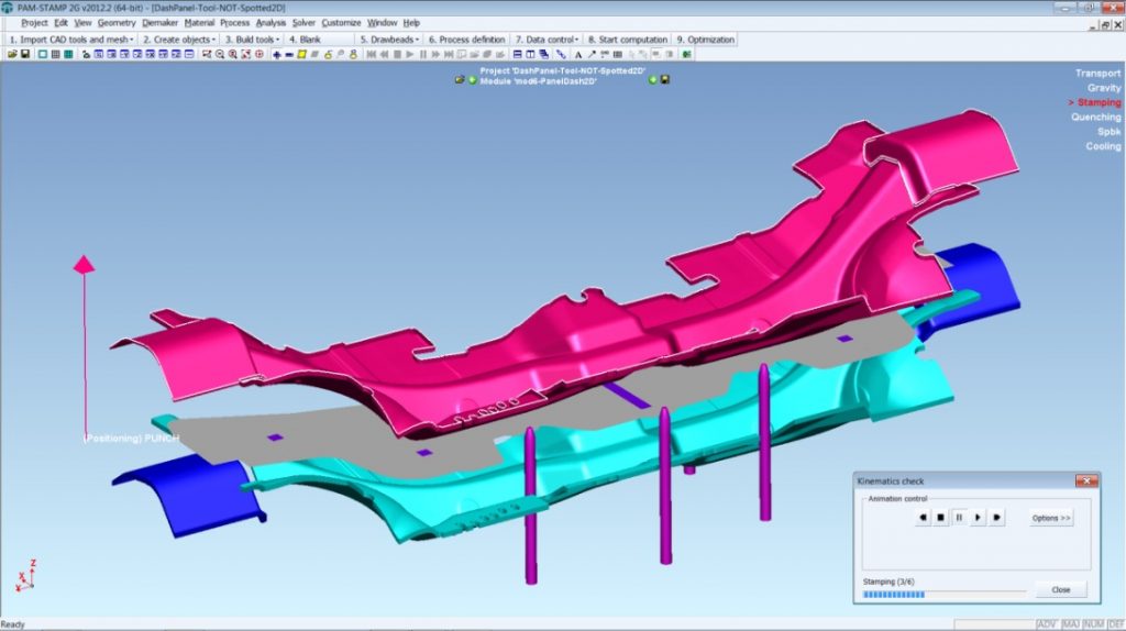
Hot forming process of the dash panel in 6 steps – Courtesy AP&T
Advanced Forming Simulation
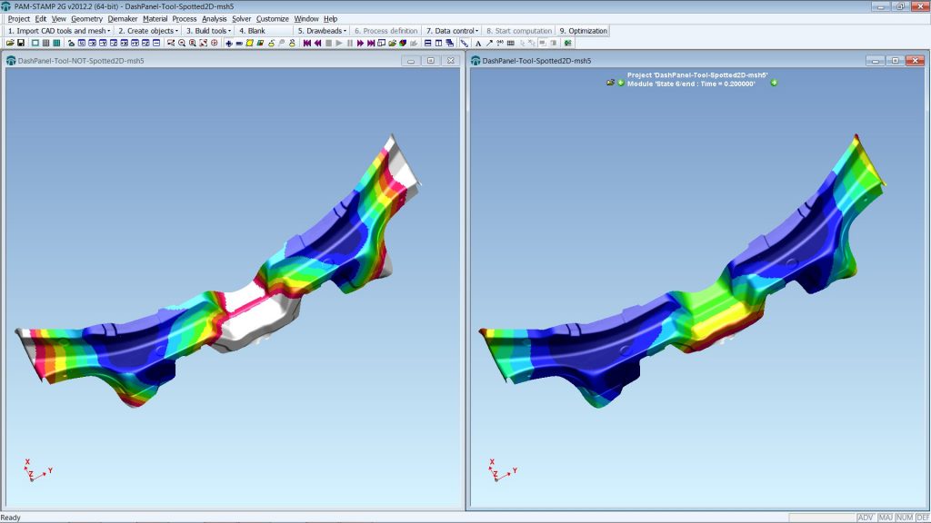
Transport – stamping – quenching
Spotting the die face
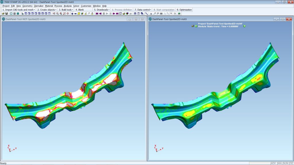
Temperature at the end of quenching above the allowed value in the not spotted die (left) and all temperature levels below the maximum allowed temperature (right) in the spotted die – Courtesy AP&T
Advanced Forming Simulation
Transport – stamping – quenching – springback – cooling on air
Spotted die face – realistic heat transfer to the die as in production
Precise determination of the part temperature and phase proportions when it comes out of the die
Part distortion – The deviation of the part from nominal shape depends strongly on the maximum temperature level after quenching
Distortion due to cooling on air after quenching in the not spotted die (left) and in the spotted die (right) – Courtesy AP&T
Partially Hardened And Patch Blank
It is also possible to engineer partially hardened and patch blanks. This is how typical cooling rates look like in a partially hardened part, displayed in a dilatometer test result. On the x-axis is the temperature, on the y-axis the actual volume relative to the starting point, as a function of temperature and phase transformations.
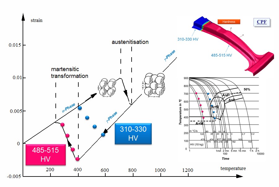
Typical cooling rates of a partially hardened part in a dilatometer diagram
This is the resulting distortion due to air-cooling. It forms after the part is taken out of the die, due to an effect similar to a bi-metal.
Distortion due to air-cooling in a partially hardened part
It is also possible to combine all those modeling techniques in a patch blank configuration.
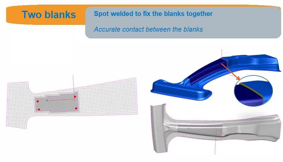
Patch blank model set up
Hot Forming – Cooling Capability Of The Die
The cooling channel analysis is done with a heat transfer model – taking into account realistic blank temperatures from the forming simulation. Heat transfer maps are coming from the CFD analysis, see next chapter. A dedicated tool is available to assemble the CAD and mesh the complex 3D die in no time.
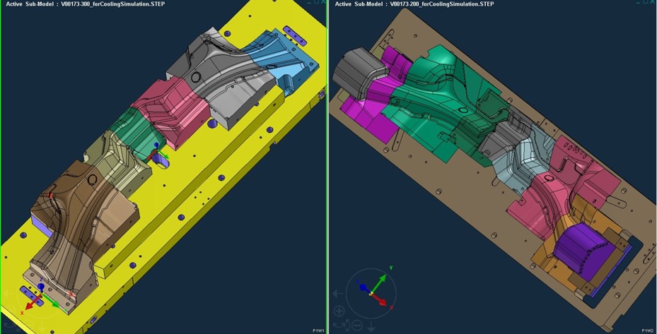
Die segments in CAD – Courtesy AP&T
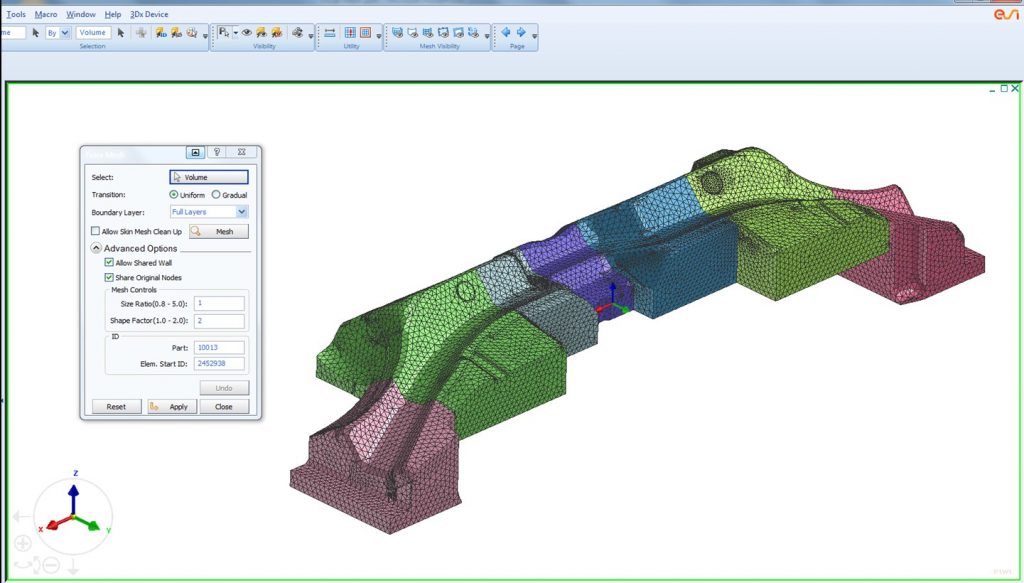
Dedicated tool meshing for heat transfer analysis – Courtesy AP&T
The heat transfer coefficient in the cooling channels is estimated at this stage to a constant value.
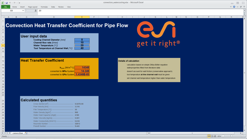
Estimation of the heat transfer coefficient in the cooling channels

Temperature of blank and die after a few strokes – Courtesy AP&T
Cooling Channel Design – CFD
The heat analysis of alloy sheet hot stamping forming process and experiments indicate that the transition process from Austenite to Martensite by controlling the sheet heating and cooling temperature is the foundation of heat forming. Only when the cooling rate reaches or surpasses the critical cooling rate, Austenite can be transformed to Martensite directly. Critical cooling rate of sheet is related to the elements of critical water flow rate, die cooling system design, cooling medium, dented die medium and the like. Under the condition, that the elements of die structure, cooling system, cooling medium and the like are defined, critical cooling rate is a constant value. As a result, through controlling critical water flow rate, hot forming transition process and hot forming requirements can be guaranteed to overcome the excessive rebound, cracking, forming force increase, easy die wear and the like in hot forming process.
ACE+ CFD solver is used to compute the coolant flow rate through the upper and lower die cooling tubes. Fig. 21 shows the pressure distribution in the upper die cooling tube at 2, 5, and 8 bars. The CFD analysis also predicts the heat transfer coefficient in the cooling tubes. The heat transfer coefficients, which are computed by ACE+, are mapped to PAM STAMP to compute the tool face temperature.
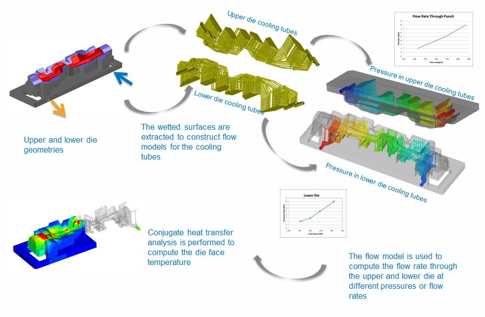
Generation of the heat transfer maps
Inlet and outlet
CFD mesh in VisCard
Pressure drop from inlet to outlet – Courtesy AP&T
Velocity maps from inlet to outlet – identification of pockets etc. – Courtesy AP&T
Die surface and die temperature, velocity, pressure, and entire heat transfer in one model
Virtual Reality
Virtual Reality is used to review the complete engineering of hot forming lines. It is even possible to integrate results computed with sheet metal forming simulation.
Virtual Reality – Hot part in the die – Courtesy AP&T
Virtual Reality – Part after quenching – Courtesy AP&T
Making engineers productive – What is available and how does it work:
Navigation:
- Topology check, cleanup and repair
- Material cost estimation
- Die face design next generation based on B-Spline geometry
- Fast link with simulation
- Accurate numerical methodsAccurate Numerical Methods – Key for Accurate Virtual Prototyping
- Geometrical drawbeads
- Springback – Kinematic Hardening Model
- Ironing
- Triple speed mode for breathtaking short simulation times
- Springback – Kinematic Hardening Model
- Precise prediction of wrinkles including folding – no numerical flattening
- Blank & Trim Line Optimization
- (Multi-operation) compensation
- Virtual prototyping of the full stamping chain
- Cosmetic defects
- Customization
- High quality results without tradeoffs in cost and time
- Hot Forming, End-to-End Virtual Prototyping
- Chaining with manufacturing engineering and assembly prototyping
- Virtual Reality
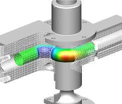
Chaining with manufacturing engineering and assembly prototyping
In the previous section, the fabrication of components including the physics of materials has been tackled. In an automotive manufacturing process, the components are then assembled in the body shop. Again, shape, material properties, and stiffness are modified in this process. Product and process architects would benefit from this information, if available at the right time. To provide this information at the right time is the goal of the Virtual Body Shop. In technical terms, distortion due to the assembly process and related assembly problems, the true point in the stress-strain space, stiffness properties, residual stresses, and remaining hardening capabilities are provided to product and process architects – at the right time.
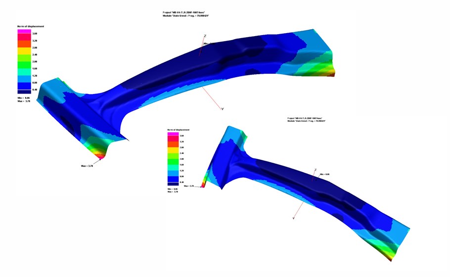
Areas of initial penetration
Computed distortion after unclamping
Residual stress after assembly (spot welds): without forming history
Residual stress after assembly (spot welds): with forming history
The virtual assembly process is described hereafter and illustrated with a few milestones.
Structural steel sheet metal parts are formed by stamping simulation,
Parts are positioned on fixtures,
Contact interference is detected between stamped geometries,
Clamping tools are closed,
Contact and distortion is updated,
Effects of pin locators etc. are taken into account,
Spot welds join components,
Effects of gap closing and thermal shrinkage is taken into account,
Contact and distortion is updated,
Assembly is unclamped and final distortion / residual stresses / true point in the stress-strain space are compu-ted and made available for any virtual investigation.
The benefits for product and process architects lie on hand:
Uncover positioning problems,
Study effects of pin locators, fixtures, clamps, welds, gaps between parts,
Find assembly problems and apply counter measures,
Save cost for prototyping and apply costly engineering only where necessary,
Improve virtual performance evaluations in the field of durability and crash behavior.
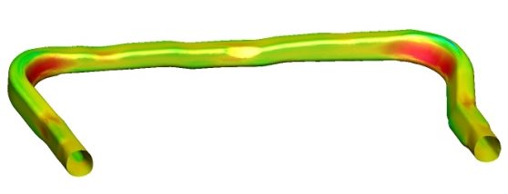
Concept Validation
Evaluated prototype – Courtesy Chrysler
Excellent correlation between computed and measured results – Courtesy Chrysler
Making engineers productive – What is available and how does it work:
Navigation:
- Topology check, cleanup and repair
- Material cost estimation
- Die face design next generation based on B-Spline geometry
- Fast link with simulation
- Accurate numerical methodsAccurate Numerical Methods – Key for Accurate Virtual Prototyping
- Geometrical drawbeads
- Springback – Kinematic Hardening Model
- Ironing
- Triple speed mode for breathtaking short simulation times
- Springback – Kinematic Hardening Model
- Precise prediction of wrinkles including folding – no numerical flattening
- Blank & Trim Line Optimization
- (Multi-operation) compensation
- Virtual prototyping of the full stamping chain
- Cosmetic defects
- Customization
- High quality results without tradeoffs in cost and time
- Hot Forming, End-to-End Virtual Prototyping
- Chaining with manufacturing engineering and assembly prototyping
- Virtual Reality
Virtual Reality
In concurrent engineering, a workflow still exists, but iterations are taken into account. The main difference from the conventional approach of product design is that all disciplines are now involved in the earliest stages of product design; they progress concurrently, so that the iterations result in less wasted effort and lost time. A key to this approach is a well-recognized importance of communication among and within disciplines. A powerful and effective tool used in the process of planning the manufacture and performance of the product is computer simulation. The next step in the production process is to make and test a prototype, that is, an original working model of the product.
Now, that next step is done in the process of virtually planning the manufacture of the product, simulating the physics of the material for each manufacturing step, and making this complex technology available for engineers and designers with process automation. Virtual reality from ESI GROUP is available to push the process of virtual prototyping to the next level.
Virtual Reality – Part after quenching – Courtesy AP&T
Making engineers productive – What is available and how does it work:
Navigation:
- Topology check, cleanup and repair
- Material cost estimation
- Die face design next generation based on B-Spline geometry
- Fast link with simulation
- Accurate numerical methodsAccurate Numerical Methods – Key for Accurate Virtual Prototyping
- Geometrical drawbeads
- Springback – Kinematic Hardening Model
- Ironing
- Triple speed mode for breathtaking short simulation times
- Springback – Kinematic Hardening Model
- Precise prediction of wrinkles including folding – no numerical flattening
- Blank & Trim Line Optimization
- (Multi-operation) compensation
- Virtual prototyping of the full stamping chain
- Cosmetic defects
- Customization
- High quality results without tradeoffs in cost and time
- Hot Forming, End-to-End Virtual Prototyping
- Chaining with manufacturing engineering and assembly prototyping
- Virtual Reality
Die Face Design and feasibility/formability simulation fully integrated into CATIA V5
ESI Group’s CATIA V5 PLM based metal forming portfolio provides die designers with a powerful set of engineering solutions which addresses design and manufacturing issues directly within a powerful generative modeling PLM environment:
PAM-TFA for CATIA V5 stands for Transparent Formability Analysis integrated into the CATIA V5 environment. It is a powerful ‘inverse’ solver, offering up front part feasibility and part costing solutions.
PAM-DIEMAKER for CATIA V5 is a fully integrated workbench inside the CATIA V5 environment (including a seamless link to simulation) dedicated to die face design. It guides the user through the die face design process (tipping, binder design, addendum design, trimline development, …) with powerful and trade-oriented functionalities, from upfront feasibility studies to full final validation.
KEY BENEFITS
Super fast Die surface engineering based on B-spline geometry
Die making software features two operation modes: product development (feasibility) or tooling
You work in CATIA with a CATIA database
You can use PAM-DIEMAKER or native CATIA functions
No more hold when you need to modify the part geometry
Fast and robust part replace
Direct link with PAM-STAMP and highly automated data transfer
Fastest solver in the market, for feasibility as well as formability (make the test!)
Best simulation quality in the market
Customer Successes
“For SEAT’s Prototype Center of Development (CPD), the release of tools integrated into CATIA V5 such as PAM-DIEMAKER for CATIA V5, allows a rapid and accurate development of die design. It is very valuable to be able to perform the appropriate geometrical changes and to have these evolutions simultaneously available for machining within CATIA.
This represents a tremendous advantage in terms of productivity as well as for the final quality of our design, giving us the opportunity to perform our work in a common environment during all process phases.”
Javier Diaz Martinez, Manager of the Prototype Center of Development (CPD), SEAT S.A.
“The simulation tool PAM-DIEMAKER for CATIA V5 gave us the opportunity to perform all the steps of our work in a single environment during all phases of the development process. This brought us more speed for our cost estimation analysis, with precise blank sizing and formability simulations. We are finally more competitive when we present an offer to our clients, having strong arguments with a quality guaranteed.”
Vladimir B. Ferreira Jr., Tech Center, Tower Automotive, Brasil
Find us on Dassault Systèmes’ PLM
MarketPlace
More PAM-STAMP Applications
PAM-STAMP – A very flexible product
PAM-STAMP allows you to simulate nearly any die operation that is out there: blanking, cut-off, piercing, piercing and blanking, trimming, side cam operations, bending, forming, drawing, bulging, coining, progressive operations and also assembly operations like marriage.
The most prominent applications that are covered are listed below. You can set up and simulate them with the standard graphic user interface. It is even possible to customize and process and die operation to your needs.
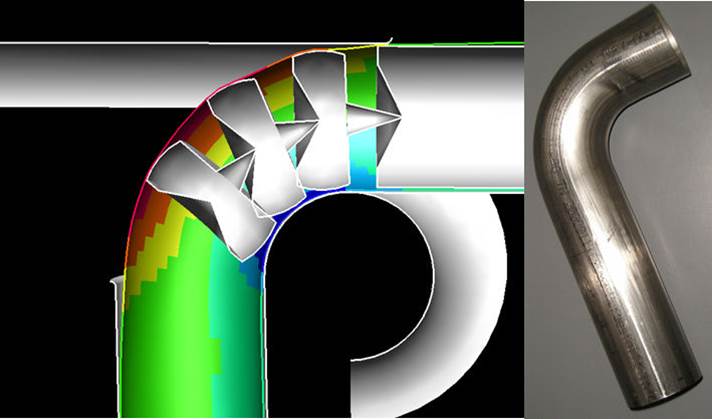
Applications
In response to market demand to form complex parts with small bend ratios, PAM-STAMP offers accurate tube bending simulation with realistic tool modelling and behavior for better forming results to avoid downstream problems.
Hydroforming is an advanced forming technique that gives the possibility of forming complex parts and improving surface quality. Liquid bulge forming and high pressure techniques can be modelled separately or combined within PAM-TUBE, covering the whole range of tube forming processes.
Its easy-to-use user environment ensures time-saving process setup and tool design and helps the user handle the complexity of hydroforming processes.
Tube Processes
Tube bending in PAM-STAMP was developed in cooperation with academic and industrial institutions. The partnership with the University of Siegen and the close cooperation with DaimlerChrysler, Audi, Schuler Hydro Forming, bu+Engineering Gmbh, hde Solutions, Eberspâcher and ThyssenKrupp Budd resulted in a robust industrial software, which allows the reliable simulation of bending and hydroforming of tubes. It includes special functions for:
Estimation of strains,
Prediction of ovalisation,
Rapid detection of the bending line,
Consideration of the welding seam,
Easy layout of the addendum,
Automatic die face creation,
Creation of multi stage process macros for efficient working.
Fully parallelized computations help to accelerate the development process and reduce cost.
Engine cradle, courtesy of Thyssenkrupp Budd
Tube Bending
CNC bending of tubes is typically not simulated, but tested and optimized on shop floor at the bending machine. However, for tube bending as intermediate manufacturing step for a hydroformed product, bending plays a crucial role. So it often needs to be simulated to achieve accurate results in feasibility determination during hydroforming. If the aim is a virtually manufactured part requested to build an assembly, it also makes no sense to neglect manufacturing operations, since they determine the performance attributes of the final part.
PAM-STAMP offers the user a virtual bending machine, which allows control of all axes with regard to forces applied, for example on clamp die, or path and velocity control for a pressure die. Boost assisted bending is also possible. The process setup starts with a simple bending curve and lets the user with basic bending know how easily advance to the bent tube.
Accurate bending simulation with precise influence of mandrel balls. Courtesy of Mewag Maschinenfabrig A
Simulation of a compound bend. Courtesy of Tenneco Automotive
Hydroforming
Hydroforming means the forming of parts by use of fluids as force transducers, compared to mechanical forces exerted by conventional presses. In niche industry sectors the medium can also be gas or plastic pellets, which is no hindrance to process simulation with PAM-STAMP. Either tubes or profiles with closed cross section are formed with inner pressure or flat blanks with one sided pressure exertion, known as Fluidcell process, or passive resistance against a mechanical forming, the so called Aquadraw process.
During hydroforming processes of parts with closed cross section, one would typically use axial punches to seal the part ends and also to push material into the forming die, to achieve a higher expansion in areas near the part ends. Parts with branching such as t-pieces also need a counter punch to control the material flow into the branching. All those technical aspects are fully covered by the possibilities inside PAM-STAMP.
In summary PAM-STAMP spans the entire virtual manufacturing chain of processes from tube bending and crash-forming or press bending over an optional consideration of annealing for stainless materials to the actual hydroforming, then trimming and optional end or further mechanical forming.
Typical customer challenges in Hydroforming are similar to conventional sheet metal forming, with some additions. Starting from the final part the hydroforming part design module PAM-TUBEMAKER supports the customer in the workflow of reverse engineering unto the required initial tube with all related manufacturing steps needed to achieve the final part. In reverse evolution that means to cover the following challenges faced by the customer:
- Determination of cross section of tube or profile part
- Design of bending line, with choice of number of bends and bending radii (typically one radius), which can be adapted to available equipment to optimize production cost
- Decision on an optional preforming operation
- Estimation of landing zone i.e. cylindrical part of tube end
- Hydroforming die preparation
- Initial tube dimensions
After an initial simulation run from tube to hydroformed part, or partial run, in case of problems, the client can decide to optimize in a second or further loop and implement it within PAM-TUBEMAKER, adapting tools and processes to improve results. Simulation results answer all questions with regard to feasibility and necessary equipment on shop floor:
Occurrence of local thinning, cracks or wrinkles
Need for specific lubrication, or possibly cam operation
Deviation of achieved form from CAD and also spring back of part
Required maximum pressure and related to that, closing force i.e. press size
Max. pressure and investigated axial feed/force determine the size of axial hydraulic cylinders
PAM-STAMP enables the customer to test and optimize the whole Hydroforming production theatre in one environment, while leaving the choice to use PAM-TUBEMAKER as starting point, or using available CAD data for all tools and parts to the customer. At the end of the day, all necessary data and information to deliver a reliable offer and feasibility statement are readily available
Sample part (real). Courtesy of Fischer Hydroforming GmbH
This part has a maximum expansion of ~50% on the left side of the picture, and a manual try-out of the pressure-feed curve will normally give a clear failure:
Rupture in indicated areas
After a run with the automatic solver, the rupture has disappeared:
No rupture – safe for manufacturing
Applications
The continuing trend of increasing the number of variants in a car while lowering the number of cars produced requires cost effective manufacturing methods and body in white concepts like roll hemming. This procedure is very flexible and requires only moderate investments. It is the target of this simulation to avoid fixtures, programming and tests during the prototype phase and pilot series.
Courtesy of UBS
Besides an optimal and error-free hemming process, the focus of the simulation is on the resulting shape deviation of the assembly caused by the spring back of the components and the hemming. The “roll in” of the final outer edge can also be evaluated.
A user-friendly interface inside PAM-STAMP defines the physical process similarly to the programming of a hemming roll guided by a robotic arm. This allows one to systematically optimize existing experience and stratégies to control possible resulting shape deviations. The position of the part’s trim lines that are essential for hemming can be optimized for the proceeding operation sequence of the respective single parts.
PSA PEUGEOT CITROËN use PAM-STAMP for Successful Roll Hemming Simulation on Vehicle Assembly Lines
Read the full Customer Success.
Roll hemming of a door
“The most significant state-of-the-art physical parameters identified by PSA’s hemming specialists were integrated into PAM-STAMP. Validated through real-life industrial cases, this new tool has quickly become essential to guarantee successful product definition and process reliability.”
Patrice Auger, R&D Manager for Assembly Processes, PSA-Peugeot-Citroën
Applications
DESCRIPTION OVER!!!
Applications
Superplastic forming with PAM-STAMP
Superplastic forming is a peculiarity in the mechanical behaviour of certain aluminium and titanium alloys, whereby extremely high levels of ductility can be obtained, allowing the successful forming of challenging shapes which would be otherwise impossible. Used in the Aerospace industry for many years, it is increasingly used in Automotive industry for low volume vehicles.
However – designing this process to make sure the full potential in these expensive materials is used is complex and difficult. PAM-STAMP has built-in modules to help finding the optimal process layout and process parameters to optimize process time and material usage.
Superform USA relies on PAM-STAMP to iteratively design complex tools and prove feasibility virtually
Download the full Customer Success
“PAM-STAMP has transformed the speed with which we can develop thickness predictions and forming cycles.While we deploy our intuition, experience and creativity to design the tools, PAM-STAMP lets us test the feasibility of our ideas without cutting metal.”
A.J. Barnes, Technical Vice President of Superform USA
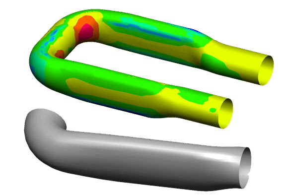
Original 23 piece welded design (left) and one-piece design optimized for SPF (right)
Applications
Stretch Forming with PAM-STAMP
There are several variations of Stretch forming processes, ranging from stretch bending of profiles, to stretch forming of panels, from fuselage skin panels, to wing leading edges.
Engine thrust reverser interior skinCourtesy of Triform Press
The process is quite delicate, and it’s important to find the correct balance of process parameters to get good quality parts, and avoid failures – particularly when the cost of raw materials for Aerospace grade aluminium and titanium is so high. PAM-STAMP is widely used in the Aerospace industry for predicting the forming quality of parts made with this type of process. Also the complex kinematics which are in the nature of stretch forming can be analysed and optimized using PAM-STAMP. Also springback can be calculated and the compensation thereof.
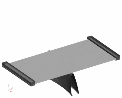
Wing leading edgeCourtesy of Triform Press
For the animated stretch forming process above three types of forming were evaluated. Draw forming, hydroforming and stretch forming. Ultimately, stretch forming gave the best overall forming results. More consistent final thickness, reduced springback and the elimination of tool marks on the outer surface.
Applications
Rubber-pad Forming with PAM-STAMP
For small volume manufacturing, mainly in aerospace, rubber-pad forming offers an interesting manufacturing technique – allowing very complex shapes. Also for exclusive automotive outer parts a superior surface quality can be achieved – as there is no punch in contact with the part. With PAM-STAMP, the rubber-pad forming process can be defined virtually to find the best process parameters for pressure build-up etc. Also springback can be calculated and the compensation thereof.
Harbin Aircraft Industry successfully implements rubber pad forming simulation using PAM-STAMP
Download the full Customer Success
“ With PAM-STAMP, we can successfully control the quality of our products. What’s more, both the cost and the time can be decreased by thirty or even fifty percent. It’s become an essential tool for our job.”
Mr. Liu Junji, Vice-CTO of Harbin Aircraft, Industry Group Co. Ltd
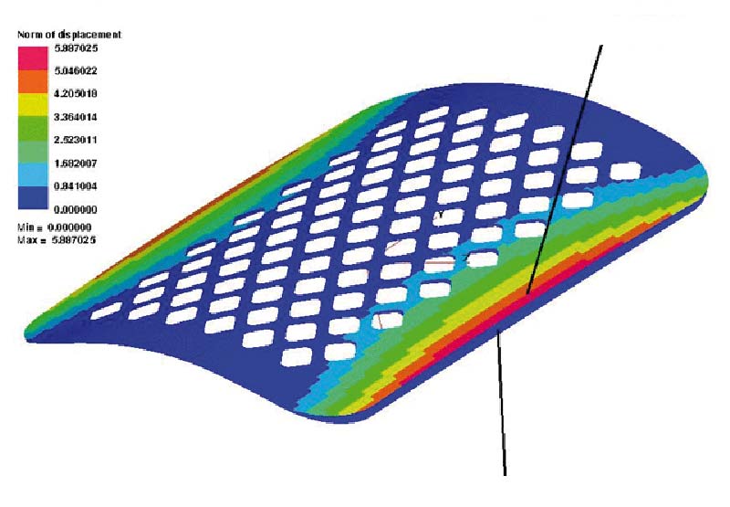
Springback compensation result on the final part
Készen áll a licenc megszerzésére?
Több információt szeretne?
About ESI Group
Founded in 1973, ESI Group is a leading innovator in Virtual Prototyping solutions and a global enabler of industrial transformation. Thanks to the company’s unique know-how in the physics of materials, it has developed and refined, over the last 45 years, advanced simulation capabilities. Having identified gaps in the traditional approach to Product Lifecycle Management (PLM), ESI has introduced a holistic methodology centered on industrial productivity and product performance throughout its entire lifecycle, i.e. Product Performance Lifecycle™, from engineering to manufacturing and in operation. Present in more than 20 countries, and in major industrial sectors, ESI employs 1200 high level specialists. In 2019, its turnover was 146M€. ESI is headquartered in France and is listed on compartment B of Euronext Paris. For further information, go to www.esi-group.com.